


|
|
|
|
This week I want to ask for references - references on a cool relationship between Julia sets and the Mandelbrot set. Then, we'll delve further into electrical circuits and analogous systems. No more rational homotopy theory, I'm afraid! There's a lot more to say, but I've been thinking about other things. These days I'm trying to crank out one This Week's Finds every week. I may give up on that soon... but I want to finish this one today, and it's 9 pm, and I haven't had dinner.
First: if you're into n-categories, you have to check out Carlos Simpson's new book:
1) Carlos Simpson, Homotopy theory of higher categories, draft available as http://hal.archives-ouvertes.fr/hal-00449826/fr/
It's very readable, with a long historical introduction that'll help you understand the motivations behind current work, and a warmup section on strict n-categories - which are relatively easy - before diving into the subtleties of weak ones. It compares many approaches to weak n-categories before explaining his own.
This could be the book the world has been waiting for! And he's asking for comments and corrections, so you can help make it better.
Next: a little music. Mike Stay pointed me to a great video illustrating the first piece from Bach's Musical Offering. Jos Leys did the animation, while a physics blogger with the monicker "Xantox" played the music:
2) Jos Leys, http://www.josleys.com/Canon/Canon.html
3) Xantox, Canon 1 a 2, at his blog Strange Paths, http://strangepaths.com/canon-1-a-2/2009/01/18/en/M
This is a "crab canon", meaning roughly a melody that sounds good when you play it both forwards and backwards, simultaneously. Bach wrote it after Frederick the Great invited him to the Prussian court in Berlin. When Bach arrived, he was asked to test the king's new pianos. The king proposed a musical theme and asked Bach to improvise a fugue based on it.
Legend has it that Bach immediately improvised two: one for three voices, and one for six! And later, after returning to his home in Leipzig, Bach composed a set of canons and a trio sonata featuring the king's theme, and sent the whole lot to Frederick as a "Musiche Opfer", or musical offering.
The whole Musical Offering is a tour de force - the sort of highly patterned thing you'd expect mathematicians to like. It consists mainly of "strict canons". In a strict canon, first you start playing one melody, called the "leader". Then, while that melody is going on, you start playing another, the "follower", which is an exact copy of the leader - except perhaps transposed to a different pitch.
The hard part is to make the leader and follower fit beautifully when they're both going on. If you need to bend the rules to make your canon sound better, that's okay - but then it's not "strict".
A crab canon, which is very rare, bends the rules by letting the follower be an upside-down version of the leader. This style is not for wimps who can't write a good strict canon: it's for people like Bach who find strict canons insufficiently challenging.
The crab canon is not the only tricky feat in the Musical Offering. For example, the fifth piece is a "spiral canon", designed to sound good if you play it over and over, but going up a whole step each time. And the eighth piece is a "mirror canon" Here the follower is an upside-down version of the leader!
I first learned this stuff here, back when I was a teenager:
4) Douglas Hofstadter, Gödel, Escher, Bach: an Eternal Golden Braid, Basic Books, 1979.
I feel sort of silly recommending this book. You must have already read it! But maybe not. I can imagine various good excuses. Maybe you were just recently born, or something. Anyway: if you like logic, self-reference, goofiness, puzzles and puns, and you haven't read this book yet, do it now! But if you hate such things, you're excused. Hofstadter's humor might grate on some people's nerves.
While it's fun to read about crab canons, and fun to listen to them, you may have trouble fully appreciating them unless you see the score while you're listening. And that's one reason the video by Jos Leys and Xantox is so great.
For more on the Musical Offering, try these:
5) Timothy A. Smith, Canons of the Musical Offering, http://strangepaths.com/canon-1-a-2/2009/01/18/en/
6) Tony Phillips, Math and the Musical Offering, http://www.ams.org/featurecolumn/archive/canons.html
Next: there's an incredibly cool relationship between the Mandelbrot set and all the Julia sets. Somehow somebody neglected to tell me about it when I was first learning about fractals. They ought to be sued! I just learned about it from Jesse McKeown over at the n-Category Café, and I want some good references on it. I don't understand it as well as I'd like! But I can show it to you.
Consider this function of two complex variables:
z |→ z2 + c
If we fix a number c, this function defines a map from the complex plane to itself. We can start with any number z and keep applying this map over and over. We get a sequence of numbers. Sometimes this sequence shoots off to infinity and sometimes it doesn't. The boundary of the set where it doesn't is called the "Julia set" for this number c.
On the other hand, we can start with z = 0, and draw the set of numbers c for which the resulting sequence doesn't shoot off to infinity. That's called the "Mandelbrot set".
Here's the cool relationship: in the vicinity of the number c, the Mandelbrot set tends to look like the Julia set for that number c. This is especially true right at the boundary of the Mandelbrot set.
For example, this is the Julia set for c = -0.743643887037151 + 0.131825904205330 i:
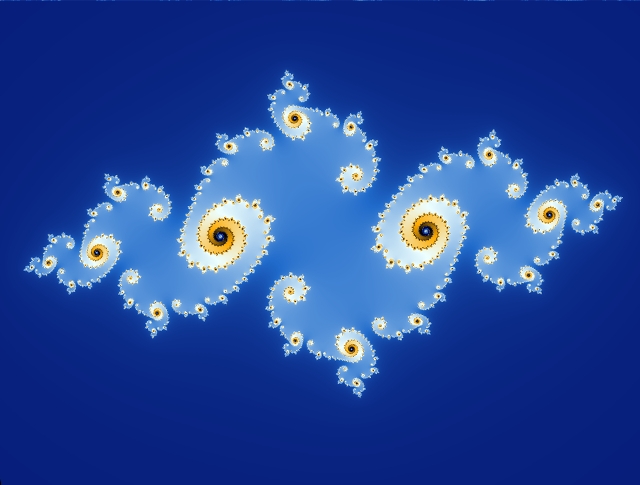
while this:

is a tiny patch of the Mandelbrot set centered at the same value of c. They're shockingly similar!
7) Wikipedia, Mandelbrot sets: relationship with Julia sets, http://en.wikipedia.org/wiki/Mandelbrot_set#Relationship_with_Julia_sets
This is why the Mandelbrot set is so complicated. Julia sets are already very complicated. But the Mandelbrot set looks like a lot of Julia sets!
Here's a great picture illustrating this fact. Click on it for a bigger view:
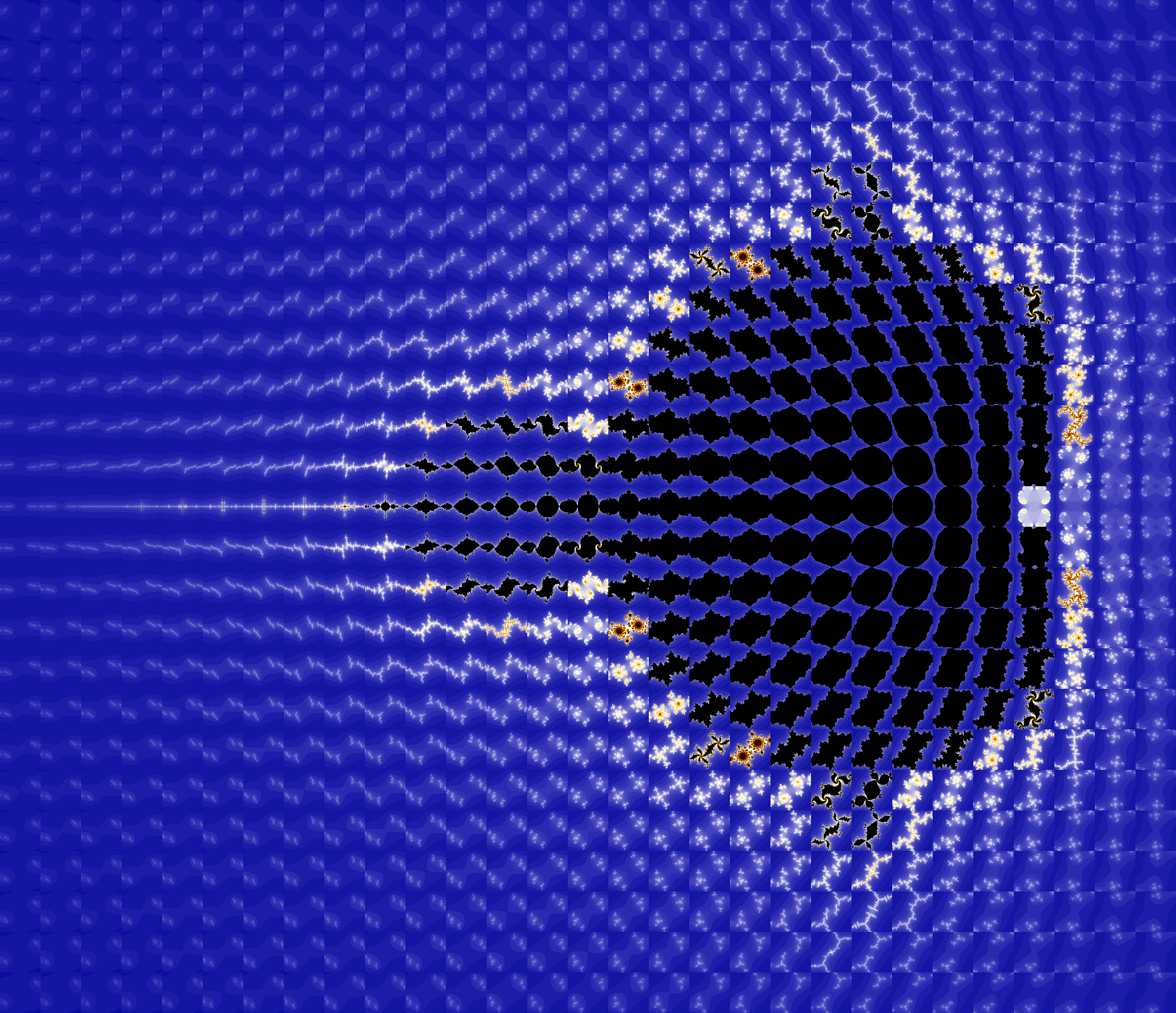
8) Wikimedia Commons, 725 Julia sets, http://commons.wikimedia.org/wiki/File:725_Julia_sets.png
It's a big picture made of lots of little pictures of Julia sets for various values of c... but it mimics the Mandelbrot set. You'll notice that the Mandelbrot set is the set of numbers c whose Julia sets are connected. Those Julia sets are the black blobs. When c leaves the Mandelbrot set, its Julia set falls apart into dust: that's the white stuff.
For an even better view of this phenomenon, try this:
9) David Joyce, Mandelbrot and Julia set explorer, http://aleph0.clarku.edu/~djoyce/julia/explorer.html
You can zoom into the Mandelbrot set and see the corresponding Julia set at various values of c. For example, here's the Julia set at c = -0.689494949 - 0.462323232 i:
and here's a tiny piece of Mandelbrot set near that point:
Does anyone know a good introduction to this phenomenon? Apparently it's the key to all deep work on the Mandelbrot set.
Last week I explained five kinds of circuit elements: resistances, capacitances, inertances, effort sources and flow sources. All these are "1-ports", meaning they have one wire coming in and one going out:
      |
      V
      |
    -----
   |     |
   |     |
    -----
      |
      V
      |
Today I want to talk about 2-ports and 3-ports. From these, we can
build all the more complicated circuits we'll be wanting to study.
But first, just for fun, here's some very basic stuff about one of the
1-ports I just listed. Namely: effort sources.
We see plenty of effort sources in everyday life. Indeed, all the technology in a modern home relies on them!
For starters, batteries try to act like constant voltage sources. For example, a 9-volt battery tries to provide
V(t) = 9
Why do I say "tries"? Because this is an idealization. If you take a perfect constant voltage source and connect its input and output with a perfectly conductive wire:
        ________
       /        \
      |          |
      V          |
      |          |
    -----        |
   |     |       |
   |     |       |
    -----        |
      |          |
      V          |
      |          |
       \________/
you'll get an infinite current! In reality, if you connect the two
terminals of battery with a highly conductive copper wire, you'll get
a short circuit: a large amount of current which winds up destroying
the battery.
(Particle physicists should look at the above diagram and think about how Feynman diagrams with closed loops in them lead to infinities. Category theorists should think about "traces" and how sometimes traces diverge. It is my job to make these analogies precise. But not today.)
Electrical outlets also do their best to act like voltage sources. But they put out alternating current, so the voltage wiggles like a sine wave. In America, from Canada down to Ecuador, outlets mostly try to produce this voltage:
V(t) = √2 120 sin(2&pi 60t + c)
where c is some undetermined constant. People say they put out 120 volts at a frequency of 60 hertz. But this 120 volts is the "root-mean-square" voltage. To get the "peak" voltage we need to multiply by the square root of 2, for reasons explained here:
10) Wikipedia, Root mean square: average electrical power, at http://en.wikipedia.org/wiki/Root_mean_square#Average_electrical_power
That's where the square root of 2 comes from. Also, in electrical engineering, a frequency of 60 hertz means you've got a wave that makes 60 full cycles per second, so we need a 2π in the above formula. Physicists often define frequency a different way, that doesn't require the 2π. This causes violent fistfights when engineers meet physicists.
In most of the rest of the world, outlets try to produce 240 volts at a frequency of 50 hertz, so
V(t) = √2 240 sin(2π 50t + c)
But humans can never agree on anything. So, there are also countries that do lots of other things - and countries like Brazil that do a mixture of things: 115 volts, 127 volts or 220 volts at 60 hertz, depending on where you are!
Why does Brazil use three voltages? Why did Australia convert from 240 volts to 230 in the year 2000? Why do some parts of Japan use 50 hertz current while others use 60 hertz, forcing Japanese appliances to have a switch that lets you pick which one you're using? I don't know... but now I want to. I have an endless capacity to find these puzzles electrifying, once I let go of a certain mental resistance, which impedes me.
And let's not even get started on the various types of plugs used in different countries!
11) Wikipedia, Mains electricity, http://en.wikipedia.org/wiki/Mains_electricity
12) Wikipedia, Mains power around the world, http://en.wikipedia.org/wiki/Mains_power_around_the_world
Okay, now let's talk about 2-ports and 3-ports. Remember, a 1-port looks like this:
      |
      V
      |
    -----
   |     |
   |     |
    -----
      |
      V
      |
If all we have is 1-ports, we can only build circuits by stringing
them together in series:
      |
      V
      |
    -----
   |     |
   |     |
    -----
      |
      V
      |
    -----
   |     |
   |     |
    -----
      |
      V
      |
    -----
   |     |
   |     |
    -----
      |
      V
      |
or perhaps forming a closed loop:
        ___________
       /           \
      |             |
      V             |
      |             |
    -----           |
   |     |          |
   |     |          |
    -----           |
      |             |
      V             |
      |             |
    -----           |
   |     |          |
   |     |          |
    -----           |
      |             |
      V             |
      |             |
       \___________/
This is sort of dull, though still worth understanding. To have more fun, we need some 2-ports or 3-ports!
A 2-port looks like this:
      |  |
      V  V
      |  |
    --------
   |        |
   |        |
    --------
      |  |
      V  V
      |  |
The current flowing in the left wire on top must equal the current
flowing out the left wire on bottom - that's just a rule in this game.
And similarly for the wires on the right. So, a 2-port has just two
flows, say q'1 and q'2. Similarly, it has two
efforts p'1 and p'2.
Mathematically, we specify a 2-port by giving 2 equations involving these two efforts and flows, the corresponding momenta and displacements, and perhaps the time variable t.
The most popular 2-ports are very simple. They are:
p'2 = m p'1
q'2 = (1/m) q'1
If you bought some electrical equipment in Europe and you try to use it in the US, you need a transformer - although your equipment may have one built in. The transformer multiplies the voltage by the right number. But thanks to some sad fact of life, it must also divide the current by that same number.
In mechanics, a lever acts as a transformer. If you push on the long end, the short end pushes with a force that's been multiplied by some number. But thanks to some sad fact of life, the short end moves at a velocity that's been divided by that very same number!
p'2 = r q'1
q'2 = (1/r) p'1
An example is a spinning gyroscope that's leaning completely horizontally. If you push it down slightly, its axis turns at a rate proportional to your push. So, it's trading angular velocity for torque!
Both these 2-ports "conserve energy" in the sense I described last week. Of course we need to generalize that notion a bit, since we've got more ports now! But it's easy. In the conventions we're using right now, the power absorbed by a 2-port equals
p'1 q'1 - p'2 q'2
The minus sign here is one of many that plague this subject, like flies in an impoverished, unsanitary tropical village. I would like to exterminate them all by a better choice of conventions, but I haven't figured out the best way. Luckily the signs don't really matter much. Here they seem to arise from treating the first port as an "input" and the second as an "output". In other words, instead of this:
      |  |
      V  V
      |  |
    --------
   |        |
   |        |
    --------
      |  |
      V  V
      |  |
people sometimes think of the 2-port this way:
  |           |
  |           |
  V           ^
  |   -----   |
  |  |     |  |
   --|     |--
   --|     |--
  |  |     |  |
  |   -----   |
  V           ^
  |           |
  |           |
Anyway, if we use vectors and write
p = (p1,p2)
q = (q1,q2)
then the power is some funny dot product of these vectors, namely
p' · q' = p'1 q'1 - p'2 q'2
for short. And we say the 2-port "conserves energy" if we can find some function H(p,q) such that
dH(p,q)/dt = p' · q'
Remember, H is the energy or "Hamiltonian". So, this equation means that when you pour power into the 2-port, its energy rises at exactly the rate you'd expect. And, you can check that both the transformer and gyrator conserve energy according to this definition.
Next: 3-ports! To build interesting circuits, we need the ability to hook up two 1-ports in parallel, like this:
        |
        |
        |
       / \
      /   \
     /     \
   ---     ---
  |   |   |   |
   ---     ---
     \     /
      \   /
       \ /
        |
        |
        |
But this gizmo, made of just wire:
        |
        |
        |
       / \
      /   \
     /     \
is not an n-port of any kind, since it has an odd number of wires
coming out.
So, how can we connect 1-ports in parallel using just n-ports?
This puzzle had me stumped for a while. But the answer is simple. To connect 1-ports in parallel, we need two gizmos of the above sort! And taken together, they can be viewed as a 3-port!
In other words, there's a 3-port like this:
    |   |   |
  ooooooooooooo
 o             o
 o             o
 o             o
 o             o
 o             o
 o             o
 o             o
 o             o
 o             o
  ooooooooooooo
   |   |   |
which you can use to connect two 1-ports in parallel. You just attach
them like this:
           _____________________
          /   ___________       \
         /   /           \       \
    |   |   |             |       |
  ooooooooooooo           |       |
 o             o          |       |
 o             o          |       |
 o             o         ---     ---
 o             o        |   |   |   |
 o             o         ---     ---
 o             o          |       |
 o             o          |       |
  ooooooooooooo           |       |
    |   |   |             |       |
         \   \___________/       /
          \_____________________/
What's in this 3-port? Nothing but wires:
    |   |   |
  oo|ooo|ooo|oo
 o  |   |   |  o
 o  |   |   |  o
 o  |___|___|  o
 o             o
 o   ___ ___   o
 o  |   |   |  o
 o  |   |   |  o
  oo|ooo|ooo|oo
    |   |   |
The little circles don't actually do anything here - they're just the
"packaging" that makes our 3-port seem impressive. Inside, it's
just two three-pronged gizmos made of wire. But if the customer can't
see inside, we can sell it for a lot of money! See how it works?
           _____________________
          /   ___________       \
         /   /           \       \
    |   |   |             |       |
  ooooooooooooo           |       |
 o  |   |   |  o          |       |
 o  |   |   |  o          |       |
 o  |___|___|  o         ---     ---
 o             o        |   |   |   |
 o   ___ ___   o         ---     ---
 o  |   |   |  o          |       |
 o  |   |   |  o          |       |
  ooooooooooooo           |       |
    |   |   |             |       |
         \   \___________/       /
          \_____________________/
Current flows in at the upper left. It gets split, goes through our
two 1-ports at right, gets rejoined, and exits at the lower left!
This 3-port is called a "parallel junction". Henry Paynter, who invented bond graphs - which we're gradually getting ready to discuss - also called this 3-port a "0-junction". And it's also called a "flow junction", which makes some sense, since this 3-port takes the flow coming in and divides it in two.
Just as the mathematical description of a 1-port requires 1 equation, while a 2-port requires 2, the description of a 3-port requires 3. For the parallel junction they are:
q'1 + q'2 + q'3 = 0
p'1 = p'2 = p'3
The first equation says that the total flow through is zero. That's obvious from the design: current can't flow from the top to the bottom. The other equations say that the voltage difference between points 1 and 1' equals the voltage difference between points 2 and 2', and also that between points 3 and 3':
    1   2   3
    |   |   |
  oo|ooo|ooo|oo
 o  |   |   |  o
 o  |   |   |  o
 o  |___|___|  o
 o             o
 o   ___ ___   o
 o  |   |   |  o
 o  |   |   |  o
  oo|ooo|ooo|oo
    |   |   |
    1'  2'  3'
This is clear if you know a tiny bit about electrical circuits:
the voltage on each connected component of wire is constant, at
least in the idealization we're using. That's because our wires
have zero electrical resistance. They're like resistors with
resistance 0, and we've seen that the voltage difference across
a resistor is the current times the resistance.
Our second kind of 3-port is called a "series junction". It's a different sort of black box, which you can use to connect two 1-ports in series. You just attach them like this:
           _____________________
          /   ___________       \
         /   /           \       \
    |   |   |             |       |
  ooooooooooooo           |       |
 o             o          |       |
 o             o          |       |
 o             o         ---     ---
 o             o        |   |   |   |
 o             o         ---     ---
 o             o          |       |
 o             o          |       |
  ooooooooooooo           |       |
    |   |   |             |       |
         \   \___________/       /
          \_____________________/
What's in this 3-port? Just wires, but now arranged a different way:
    |   |   |
  oo|ooo|ooo|oo
 o  |   |   |  o
 o  |   |   |  o
 o   \   \ /   o
 o    \---\    o
 o   / \   \   o
 o  |   |   |  o
 o  |   |   |  o
  oo|ooo|ooo|oo
    |   |   |
See how it works?
           _____________________
          /   ___________       \
         /   /           \       \
    |   |   |             |       |
  oo|ooo|ooo|oo           |       |
 o  |   |   |  o          |       |
 o  |   |   |  o          |       |
 o   \   \  /  o         ---     ---
 o    \---\    o        |   |   |   |
 o   / \   \   o         ---     ---
 o  |   |   |  o          |       |
 o  |   |   |  o          |       |
  oo|ooo|ooo|oo           |       |
    |   |   |             |       |
         \   \___________/       /
          \_____________________/
The series junction is also called a "1-junction" or "effort
junction". This makes sense, since the equations defining this 3-port
are exactly like the equations for the previous one, but with effort
and flow switched!
p'1 + p'2 + p'3 = 0
q'1 = q'2 = q'3
I'll let you figure out why these are true.
By the way: this "duality" between the series junction and parallel junction - the way they're the same, but with the roles of effort and flow switched - is actually the tip of a big iceberg! There's a duality between effort and flow. This duality is related to Fourier duality, since in quantum physics the Fourier transform interchanges momentum and position - the quantities whose time derivatives are the effort and flow variables in classical mechanics. But this duality is also related to Poincaré duality. For any circuit whose underlying graph is planar, there's a "Poincaré dual" circuit where we replace edges by vertices, vertices by edges - and also switch efforts and flows!
I hope to say more about this duality when I reach the more cosmic, grandiose aspects of the long story I'm telling. But if I forget, you'll have to read this:
13) Istvan Vago, Graph Theory: Application to the Calculation of Electrical Networks, Elsevier, 1985.
See the section called "The Principal of Duality", on page 77. Also, look on the web for stuff about the "Δ-Y transformation", which is a special case.
If you want to learn more about the 1-ports, 2-ports and 3-ports I've been discussing, let me again recommend this book:
14) Dean C. Karnopp, Donald L. Margolis and Ronald C. Rosenberg, System Dynamics: a Unified Approach, Wiley, New York, 1990.
It's good on the abstract concepts, it clearly lays out most of the basic analogies, and it's not very long. It seems to be a modernized version of this earlier book, which has its own homegrown charm:
15) Dean C. Karnopp and Ronald C. Rosenberg, Analysis and Simulation of Multiport Systems, MIT Press, Cambridge, Massachusetts, 1968.
For something vastly more detailed, try:
16) Forbes T. Brown, Engineering System Dynamics: a Unified Graph-Centered Approach, Taylor and Francis, 2007.
This mammoth tome is 1058 pages long, mainly because it's packed with examples. So, some of the big ideas are a bit hard to spot. But it proves these ideas are useful in many different fields!
Addenda: I thank Tim van Beek for correcting my German spelling. David Roberts says it's questionable whether Bach really composed a six-part fugue on the spot in Frederick's court: contemporary reports say so, but it may be an exaggeration. Theo pointed out that a Möbius strip is not really perfectly suited to a crab canon:
Möbius strips are cool, and the Crab Canon is cool, but they're essentially different. Notice that in the video, the two players are still going around the Möbius strip in opposite directions, and each is keeping to its own side of the strip. Moreover, in spite of visually putting in a twist, the "backwards" player is really playing the sound in a mirror, not upside-down. There's a reason Bach calls it "crab": it can be played forward and backward.Thus, the correct visualization is not a Möbius strip at all, but the orbifold with boundary formed by reflecting the rectangle in half. Making this is easy: take a piece of paper with the music written on one side, and fold it so that the music is on the outside. In this way, each side of the orbifold has half the music on it. Now start at the non-mirror end, but play both sides, reflecting through the orbifold boundary and continuing until you're back where you started.
Someone with the monicker Mixo Lydian sent me an email answering my question about why Japan has currents of two different frequencies - 50 and 60 cycles per second. As expected, there's some history involved:
The 50Hz/60Hz divide in Japan is due to historic reasons. Towards the end of the Meiji era, Japan made the switch from DC to AC. Tokyo Dento (Japan's first electric power company) adopted 50Hz German AEG generators while its rival Osaka Dento decided to adopt 60Hz American GE generators to power their respective electric grids.Neighboring regions built their electric infrastructure adopting either Tokyo or Osaka standards which has led to a east-west / Tokyo-Osaka divide which continues to the present day, the exact border being the Fuji river which runs thru Shizuoka prefecture: east of the river the frequency is 50Hz, west of river the frequency is 60Hz.
This has hilarious consequences for the town of Shibakawa-cho, Shizuoka. The Fuji river runs directly thru Shibakawa-cho: some parts of town use 50Hz while others use 60Hz! All you have to do is cross a bridge to alternate between (intentional pun)! Hope this has been helpful.
For more discussion, visit the n-Category Café.
Mathematics is not a careful march down a well-cleared highway, but a journey into a strange wilderness, where the explorers often get lost. Rigour should be a signal to the historian that the maps have been made, and the real explorers have gone elsewhere. - W. S. Anglin
© 2010 John Baez
baez@math.removethis.ucr.andthis.edu
|
|
|
|